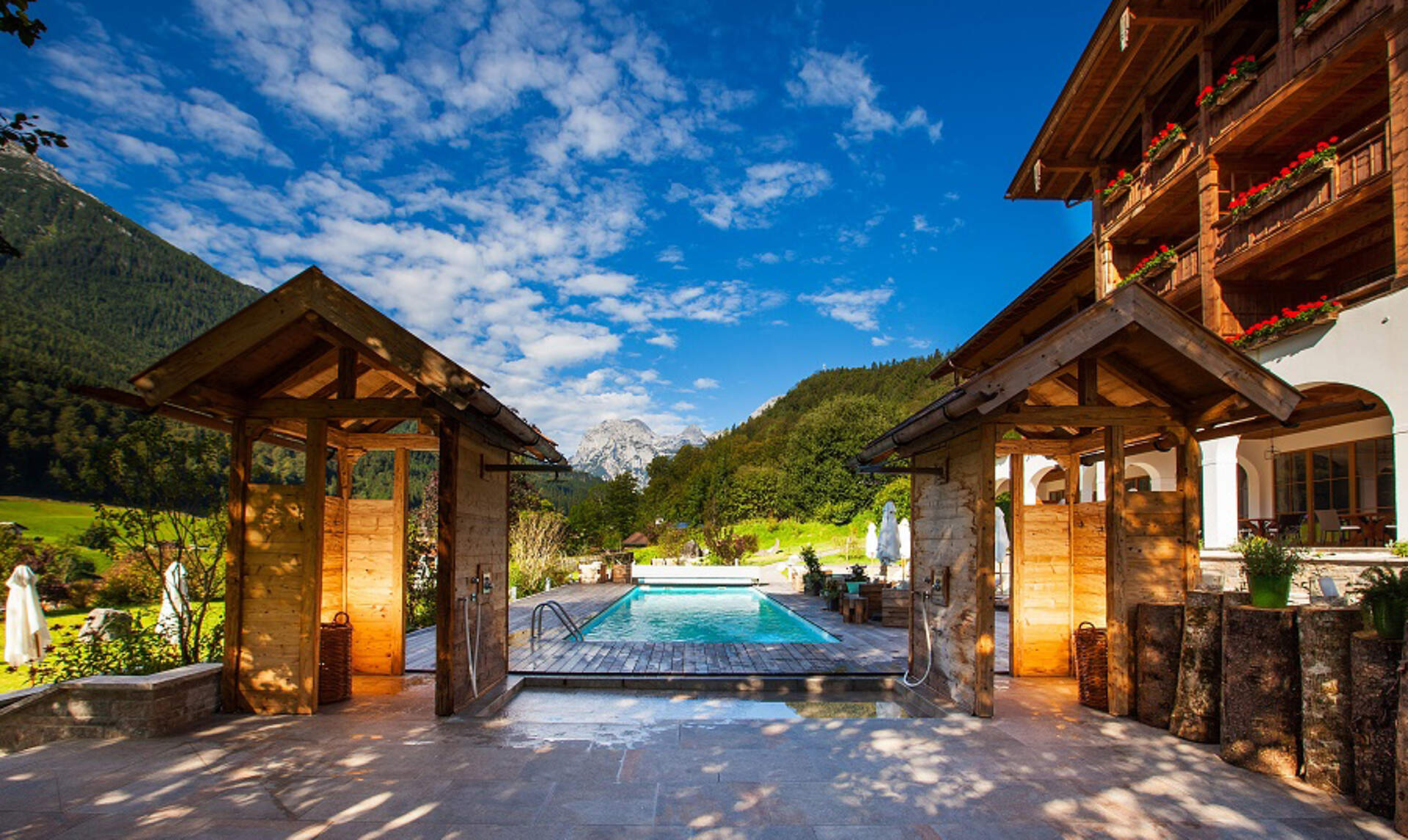
Climate-neutral mountain hotel
Change of controllers during operation
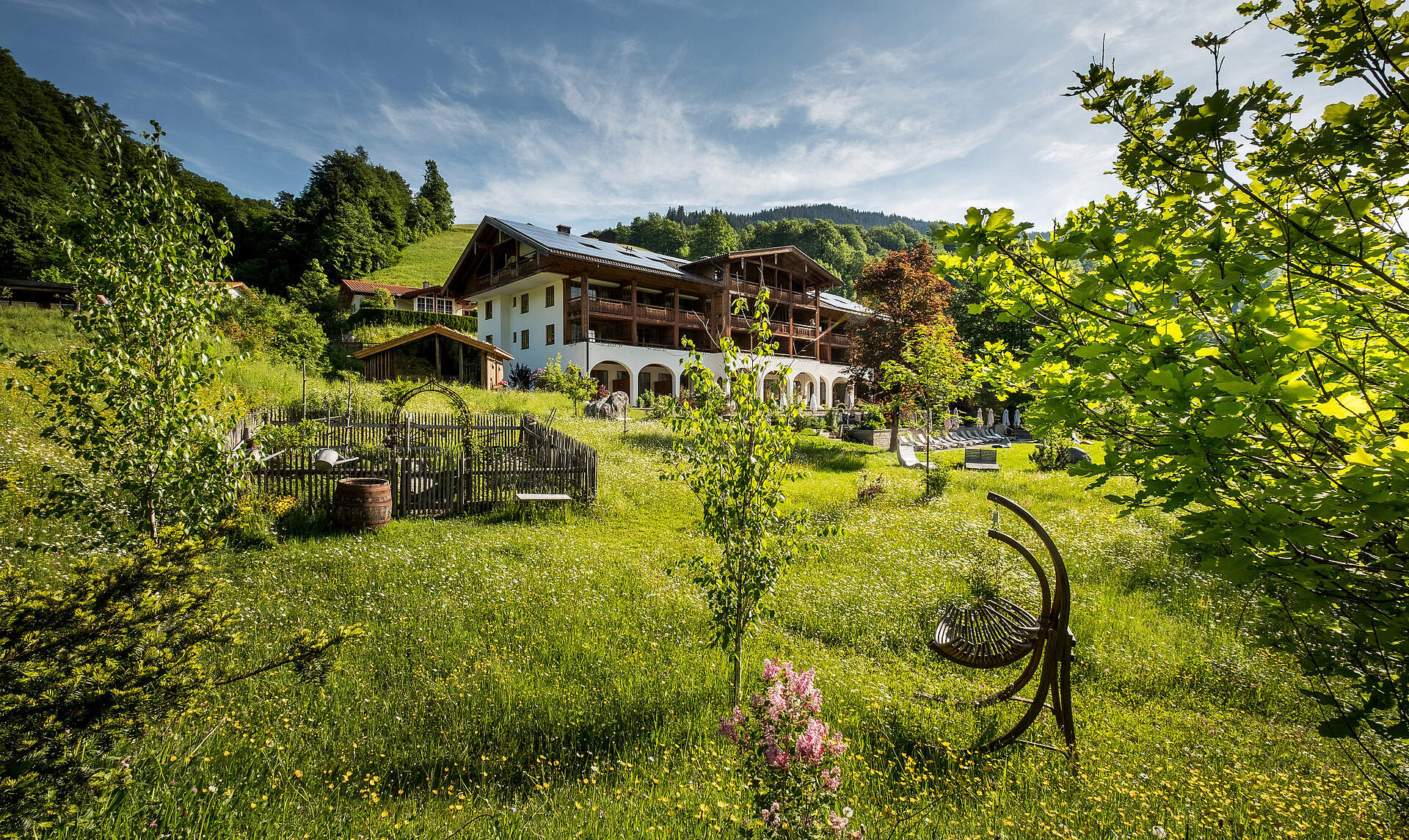
The hillside hotel with 87 rooms is supplied with heat by two cogeneration plants, roughly 100 m2 of solar thermal panels and two photovoltaic plants, producing roughly 30 kWp of heat and power.
Before the change to x2 devices as master controllers, the owners and keepers of the hotel could hardly get a good overview of the system. It was divided into several subsystems, each with their own controllers, barely any of which communicated with one another.
The biggest problem was the lack of communication between the cogeneration plants and the backup boilers.
Before: Manual operation instead of automation
Boilers had to be manually switched off during summer. If then the cogeneration plants failed, the entire building was left cold, unless the boilers were manually switched back on. Error messages of boilers were displayed only on the boiler itself. For solar panels and DHW preparation, several small controllers were in place. There was no centralized control unit, not to speak of a unified operating interface.
All of this would be simplified by the new controllers and the implementation of the web portal.
Changeover during operation
As the hotel was busy, denying the guests heating or warm water was clearly not an option. To tackle this task, the entire system (including all pre-existing controllers’ tasks) was documented and drafted into a hydraulic schematic.
As such, the new controllers were programmed beforehand and the actual switch was planned for after the heating season. Since the controllers were switched out one-by-one, the UVR16x2K for wall-mounting was deliberately chosen, instead of versions for control cabinets. Extended downtimes were avoided this way.
After: Automation and comfort
Alongside the new controllers, a new cogeneration plant (which was supplied by 100% district heating before) was built into the annex. Thanks to the new controllers, the cogeneration plant was used for heating as much as possible and to only fall back to district heating if necessary, or if the cogeneration plant was faulty. Excess heat from the annex could be supplied to the main building, increasing the cogeneration plant’s operating hours even more.
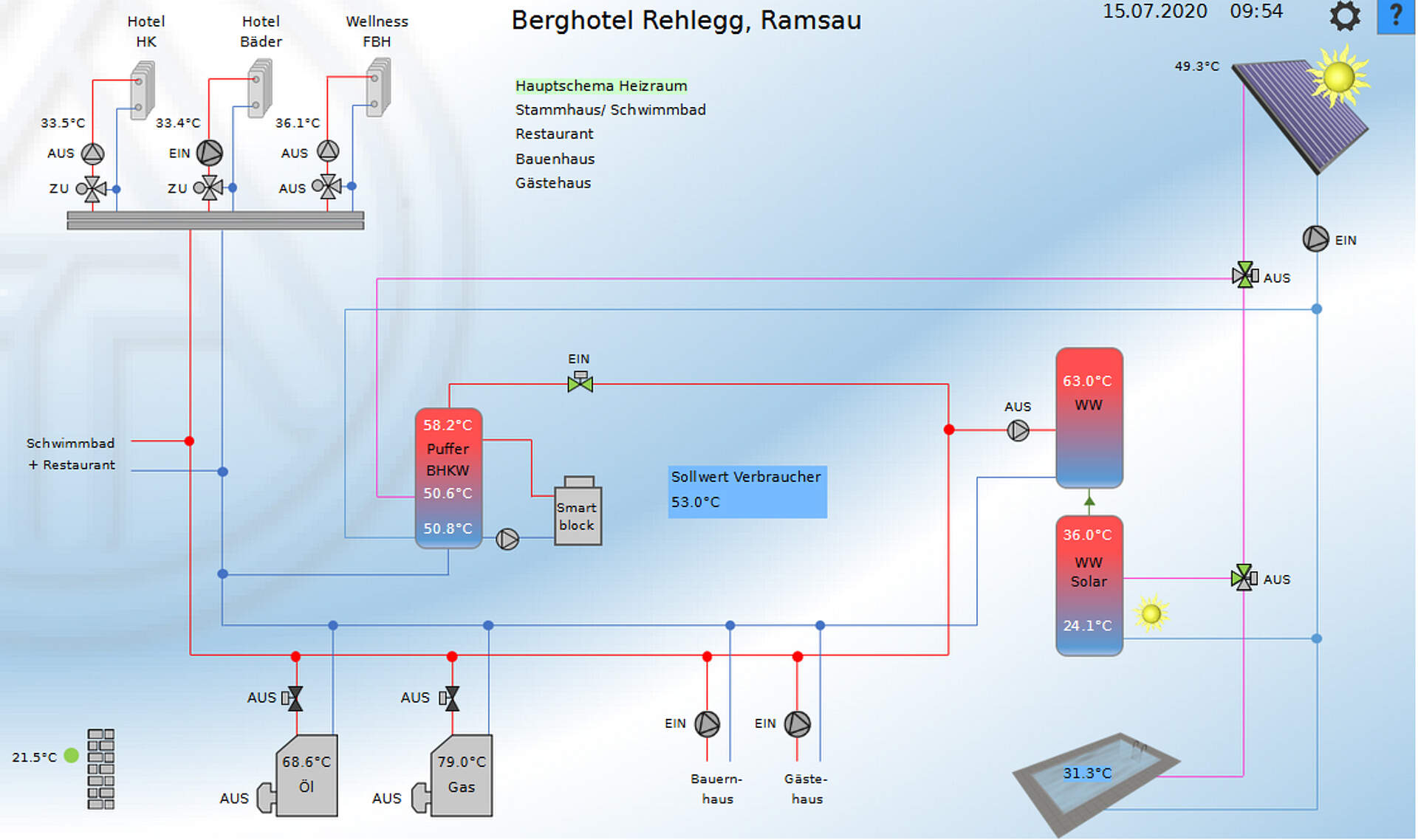
The system oversees the nominal values of all consumers and then decides whether the available heat in the buffer suffices to supply the system or not. If not, a boiler (gas or oil, specified by the operator) is fired up. Should the specified boiler encounter an issue, the other one is automatically fired up and an error message is sent via C.M.I.
An extensive messaging system ensures that staff are immediately informed about errors and malfunctions. In certain cases, an indicator lamp will light up at the reception desk to ensure a timely resolution of the problem. For example, if the cogeneration plant doesn’t begin operating after a power outage, it displays no error but also doesn’t re-enter operation on its own. In this case, a message is issued, indicating that the nominal temperatures could not be reached. Staff can then decide to either switch the cogeneration plant back on or activate district heating.
Guaranteed supply and efficiency
All these measures serve to guarantee energy supply. For a hotel, nothing could be worse than being unable to provide heat/power to guests. If the cogeneration plant experiences issues, district heating is automatically activated as a replacement. If the buffer cylinder in the annex reaches its set temperature, additional heat is rerouted to the main building. This increases the cogeneration plant’s operating hours, increasing the system’s efficiency.
Visualisation
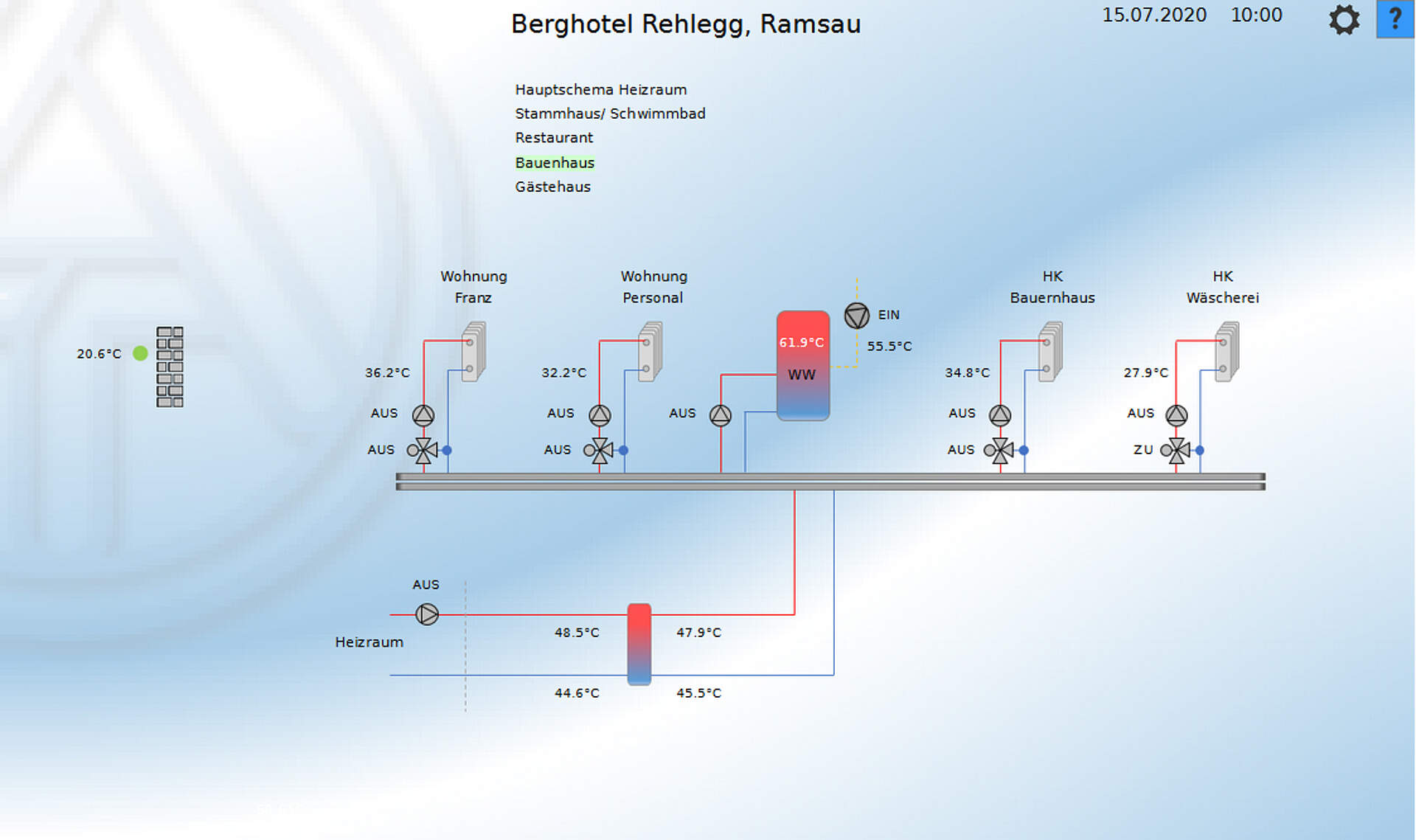
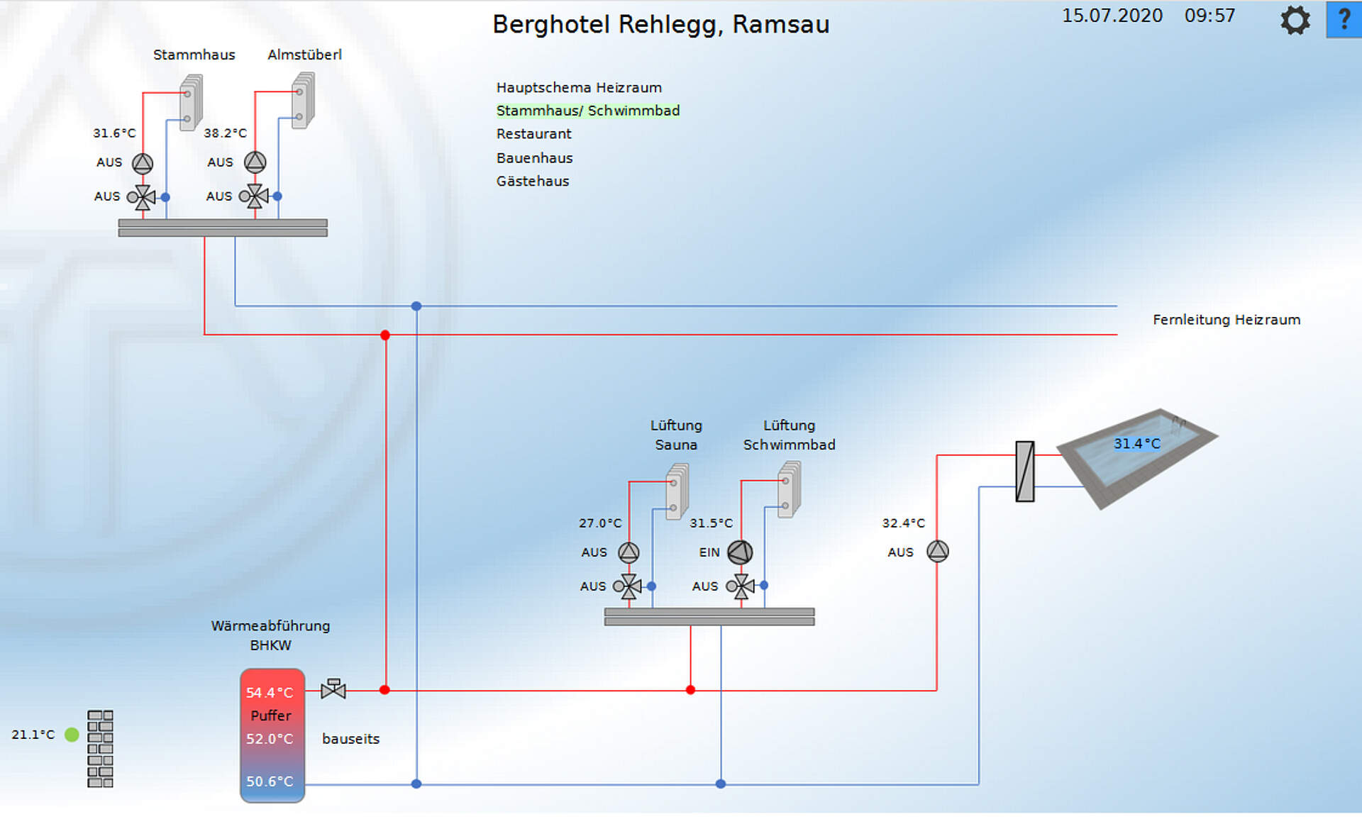
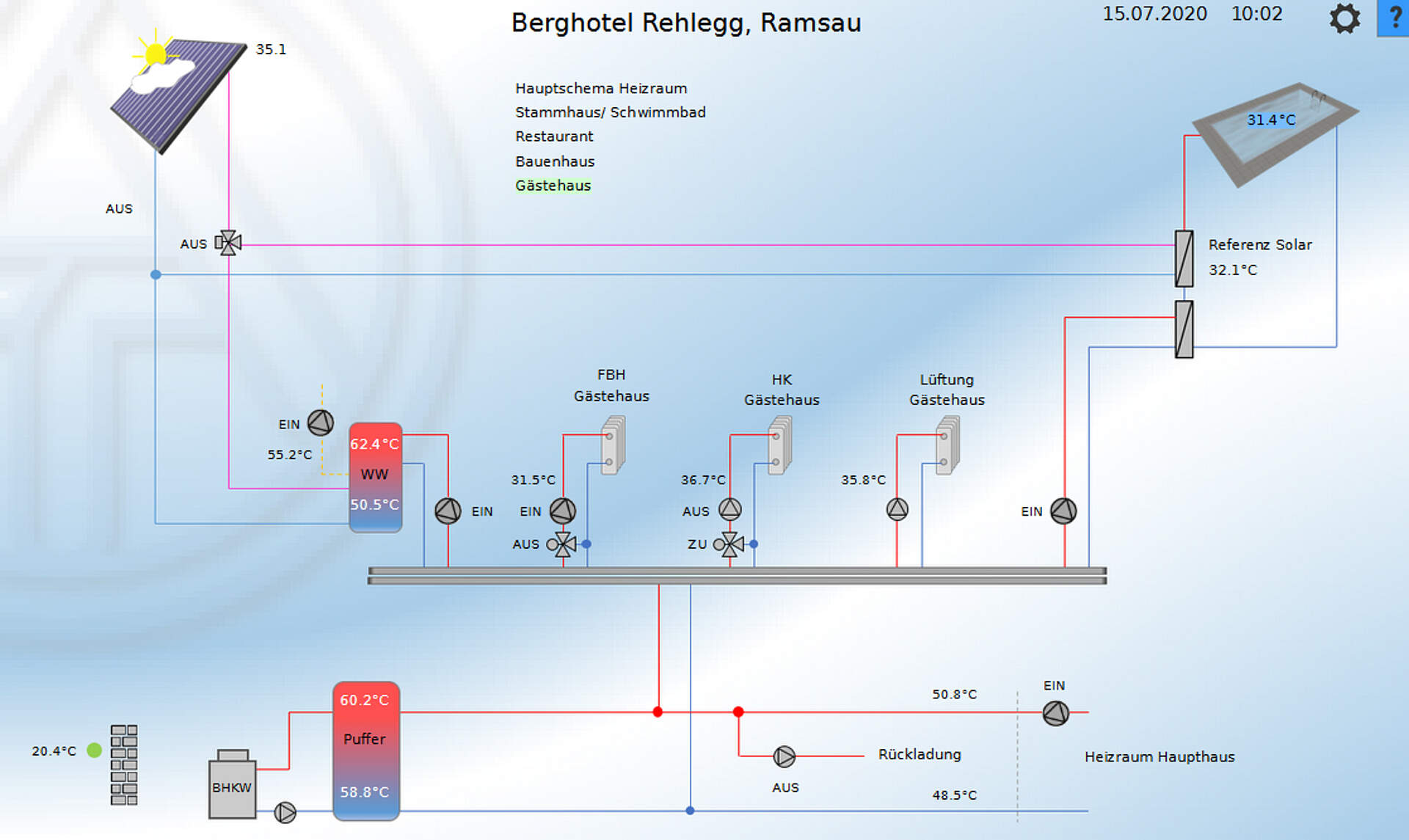
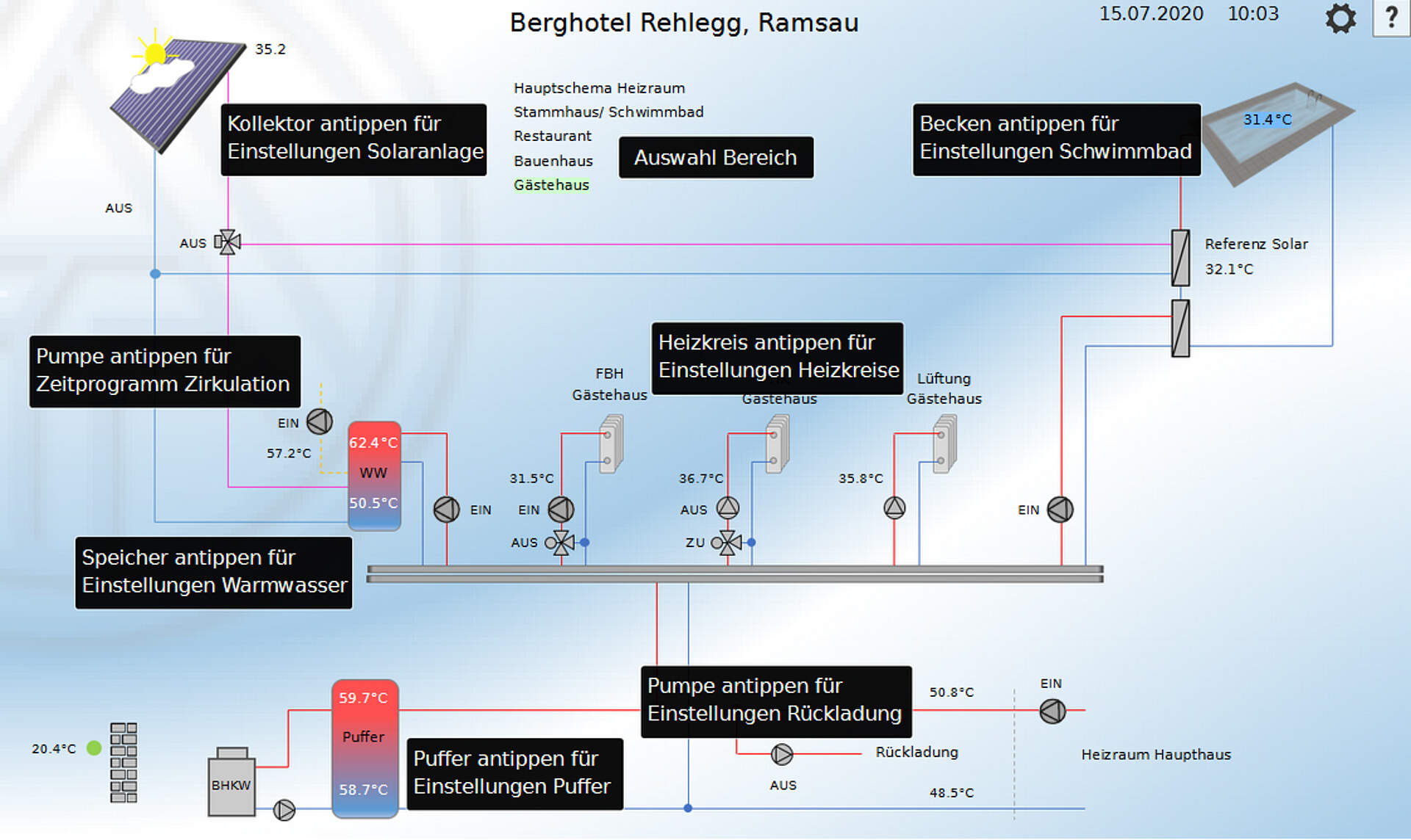
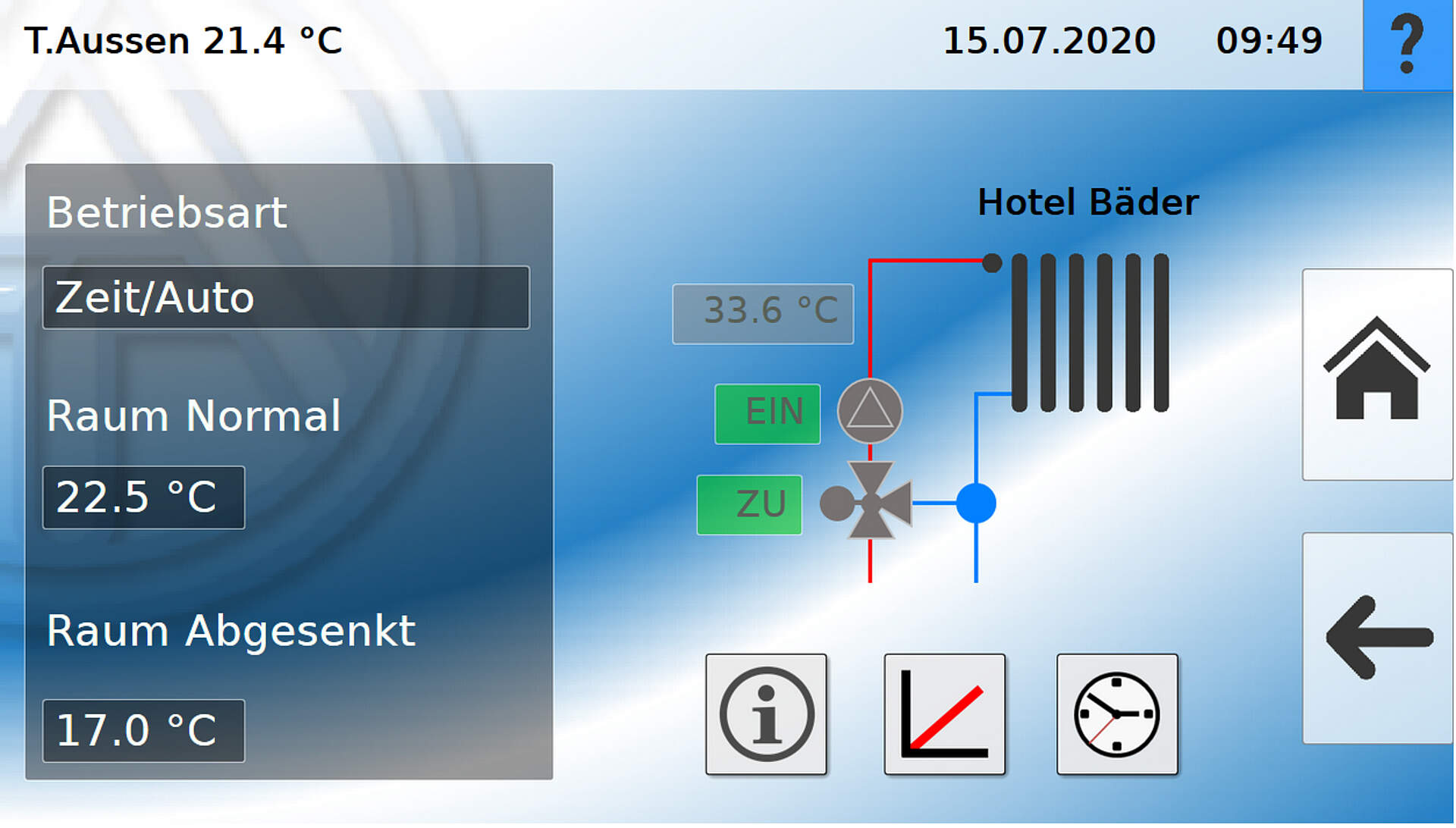
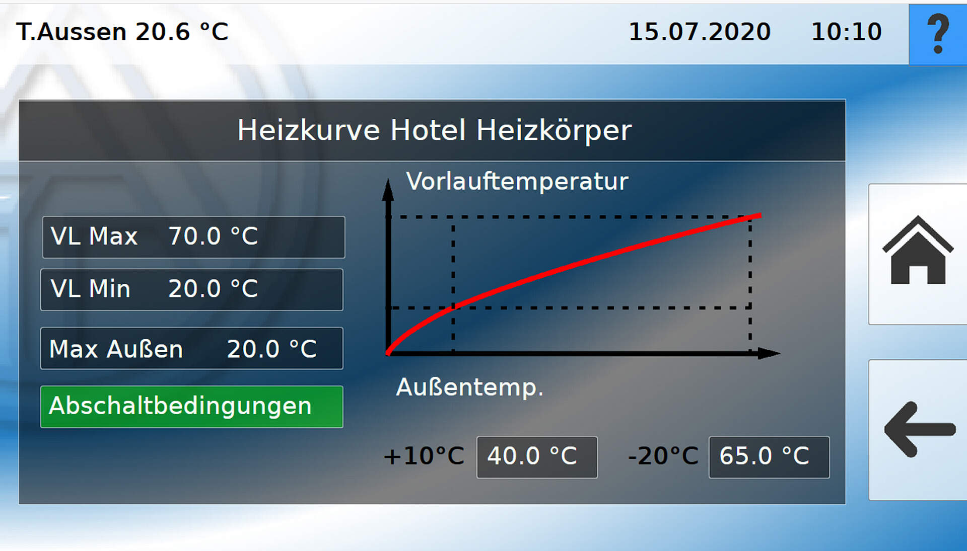
A central element of the system is the visualisation via the control and monitoring interface (C.M.I.). Every section of the building has its own main overview panel, reachable with a single tap on the starting page. Additionally, every page of the visualisation features its own help menu, giving staff necessary information wherever needed.
Conrollers
- 6 UVR16x2K
- 1 C.M.I.
- 1 CAN-MTx2 as a control unit in the pool house
- 8 CAN-UES
- 2 AC/DC converter
- several auxiliary relays
- sensory equipment (74 temperature sensors)
System
- 1 cogeneration plant in the main building (70kW thermal, 30kW electric)
- 1 cogeneration plant in the annex (30kW thermal, 16kW electric)
- 1 gas-fired heater to support cogen. plants (400 kW)
- 1 oil-fired heater as backup for the gas heater (400 kW)
- 2 thermal solar plants, totalling 100m2
- 4 heat registers for ventilation system
- 2 cylinder charging systems
- 6 circulation circuits
Consumers
- 15 heating circuits
- 1 outdoor pool
- 1 indoor pool
Buffers
- 6 buffer storages
- 1 DHW buffer storage
Dieses Projekt wurde realisiert durch:
Zeiser Regeltechnik
Büchling 1
83278 Traunstein
http://www.zeiser-regelungstechnik.de/
