Instructions for problems with the control valve
How to establish temporary emergency supply
If problems arise with the DHW preparation of a FRISTAR3 or FRISTAR3-WP, please follow these instructions:
For end users: restart
Restart the fresh water station by unplugging it, waiting about ten seconds, and then plugging it back in. This usually causes the valve to recalibrate itself and resume reliable function for a time. If the error persists repeatedly, an exchange of the valve is highly recommended.
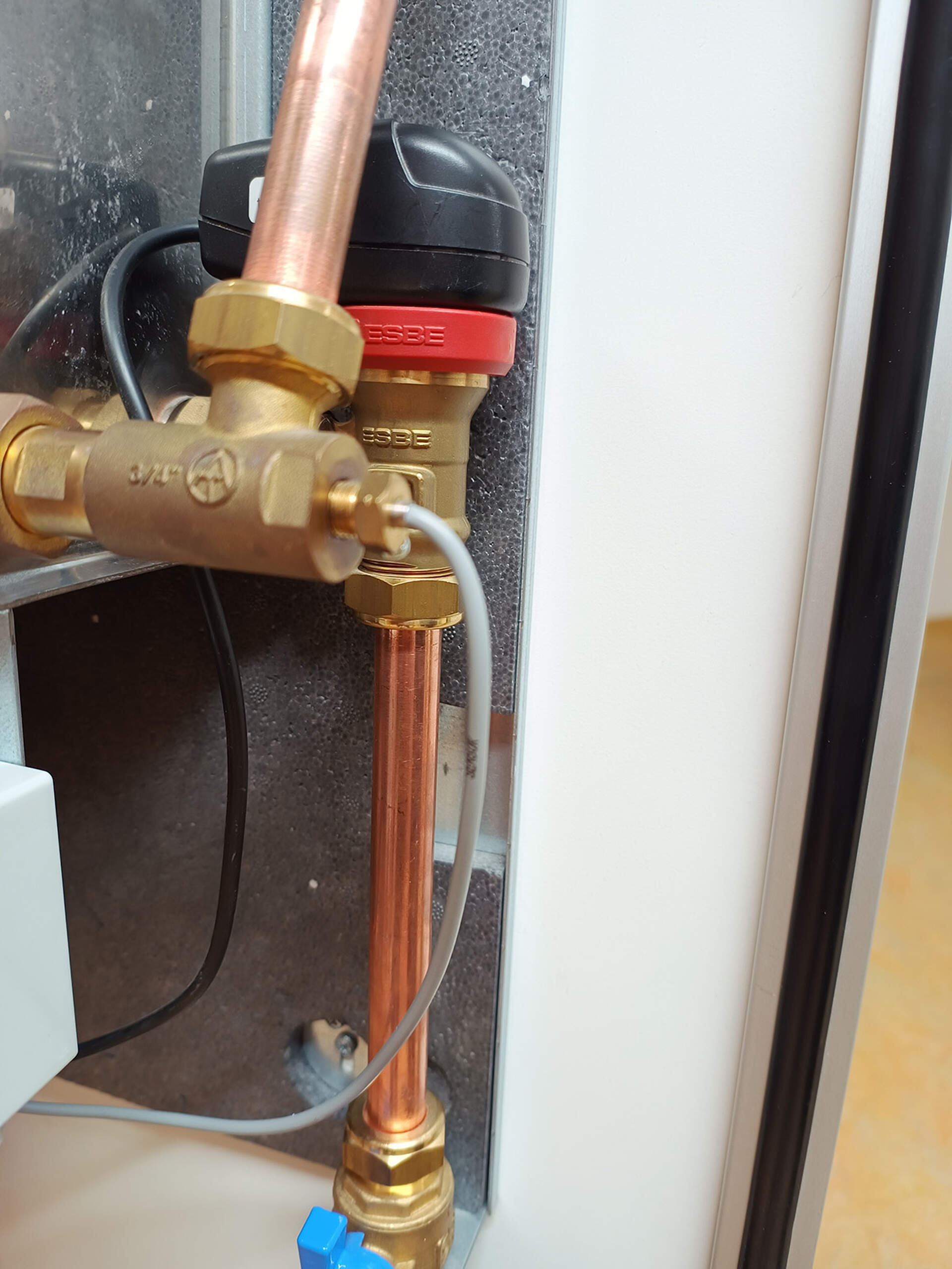
Step 2: Dismounting the valve
If the valve cannot be reactivated anymore (it remains shut), it must be removed alongside its supply line to momentarily alleviate the issue.
Required materials and tools
- 2 pipe wrenches
- 1 pc reinforced hose (min. 30cm)
- 3/4” external thread and 3/4” internal thread with union nut or
- 3/4” both sides with union nut
- 2 suitable seal gaskets
- Thin wire, max. 0,75 mm2 (about 10 cm suffices)
- Philips screwdriver (ideally PH 1) and slotted screwdriver (ideally 0.4 x 2.5) for tasks on the controller
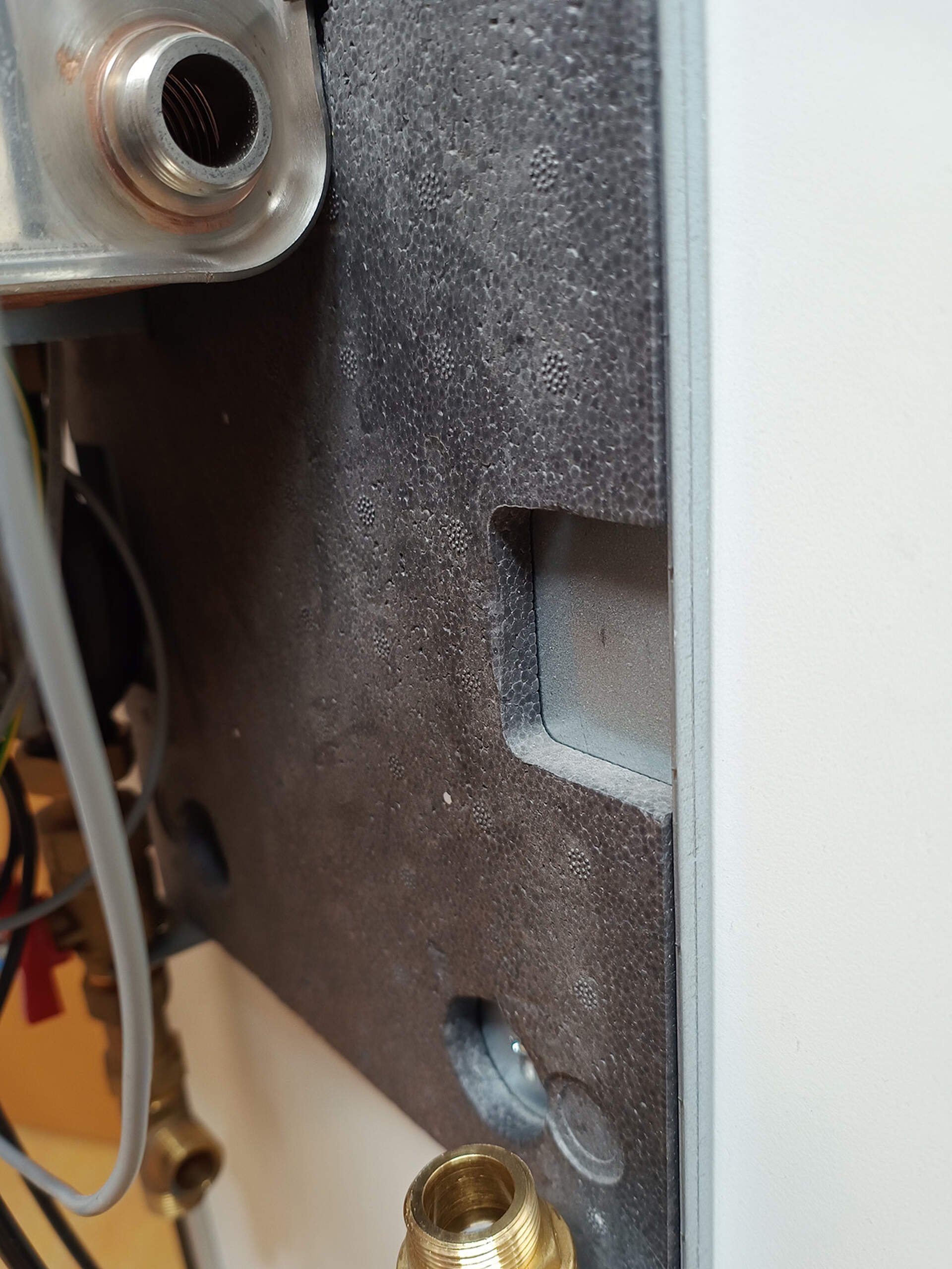
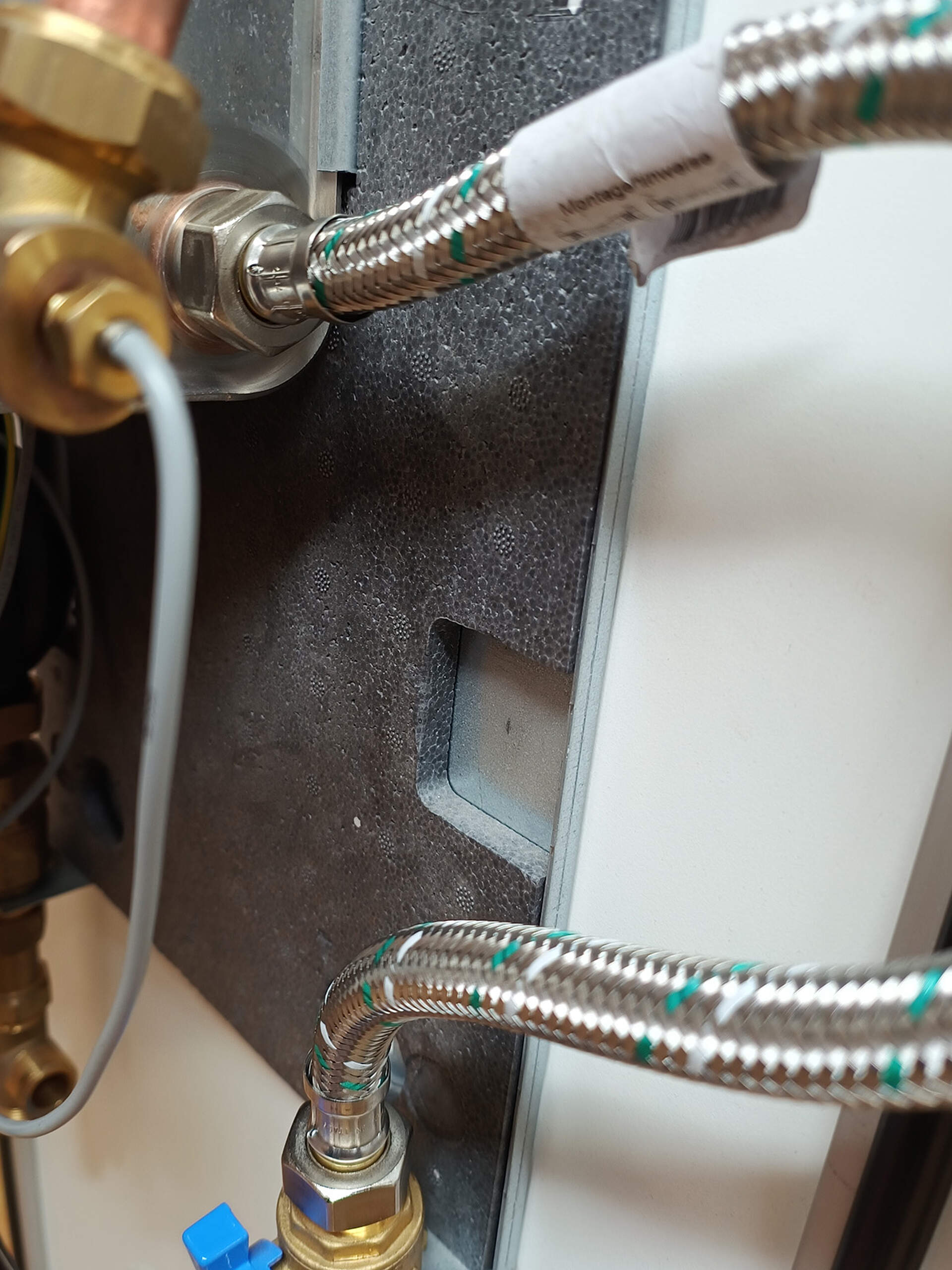
Step 3: Replacement via reinforced hose
A makeshift direct hydraulic bypass from the ball valve to the heat exchanger can be established with e.g. a reinforced hose (30cm or longer). Please note the 3/4” external thread (ext-int or int-int is possible, int with union nut) and mind the 2 suitable sealing gaskets.
Step 4: Electronics
The controller recognizes the defective valve and refuses to operate normally after starting. A small wire bridge avoids this blockage.
Cut the power supply before opening the controller. Afterwards, remove the valve’s wire from the plug on the controller’s PCB and bridge a wire across the outer two terminals of the plug.


Step 5: Reassembly and test
Reassemble the controller, supply power, and wait for ten seconds. Afterwards, tap DHW. One of two scenarios will unfold:
(1) Controller reacts to tapping
Use the knob on the front of the controllers for rough adjustment of DHW temperature. It may occur that the controller displays a valve error during the tapping of water. This can be ignored (without tapping, the error will always be displayed).
(2) Controller does not react to tapping (water remains cold at point of tap)
Cut power supply and reopen controller. Remove sensors S1 and S2 (*). Remember to mark their spots for later reconnection. The wires of both sensors should also be protected, e.g. using electrical tape. The pump can now be turned off using “Manual OFF” and turned on to 100% output using “Manual ON” when required. In Mode “Auto” the pump can be set to a fixed output using the knob on the controller.
(*) If the “Auto” mode is not required, you can also remove the sensors by unplugging their entire plug strip, rather than individual wires.


Step 6: return defective valve
Return exclusively the valve without accessories (leave union nut, controller etc. on site).
To request a replacement valve, please fill out this form. The defective valve must be returned to us, else a fee for its replacement will be incurred.