Agricultural Estate
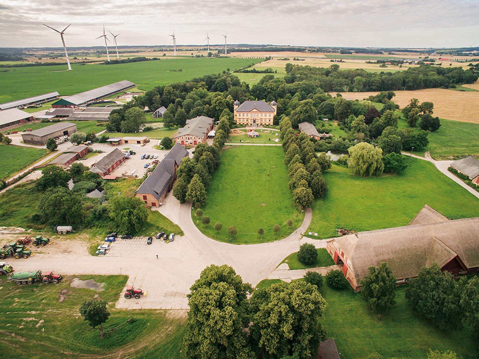
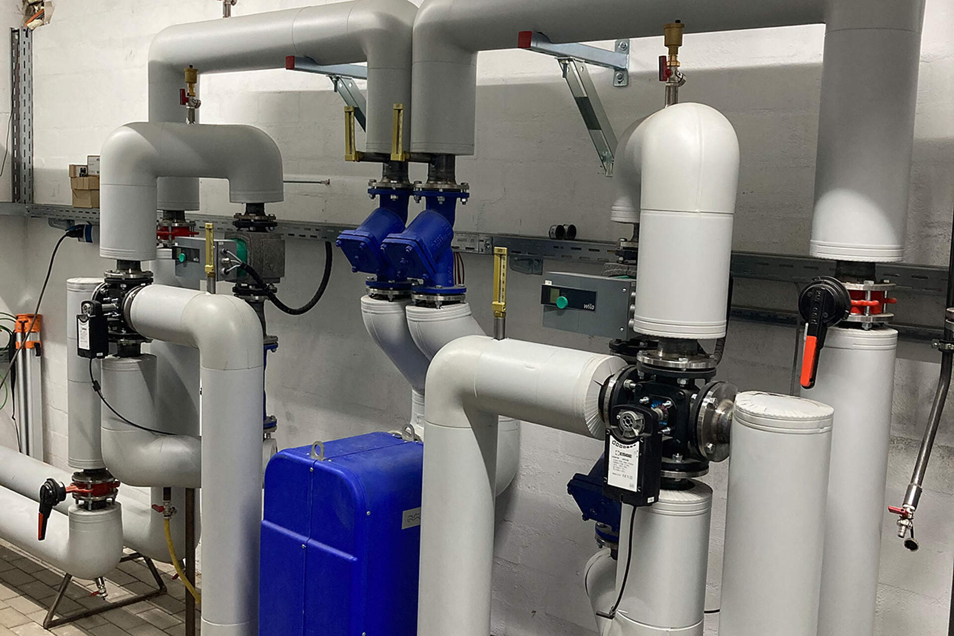
The heating concept of "Gut Hohen Luckow" has been steadily expanded and modernised in recent years. However, with the expansion of dairy farming, the energy demand grew.
A difficult starting position
- Extensive heating network
- No central documentation
- Lack of communication between the sub-areas
- too complex for employees
- uneconomical and susceptible to faults
Initially, the farm house and surrounding buildings haven been heated using solely fossil fuels. However, energy demands grew with the expansion of a dairy farm. More energy was required for hot water preparation in multiple places and pasteurising milk demanded high temperatures.
At this point, the heating networkstretches over 2,350 meters, where sources and consumers of heat had to be implemented in disadvantageous places. To better fit present conditions, constant user interference and permanent manual adjustments of armatures and pumps became necessary.
Implementation "step by step"
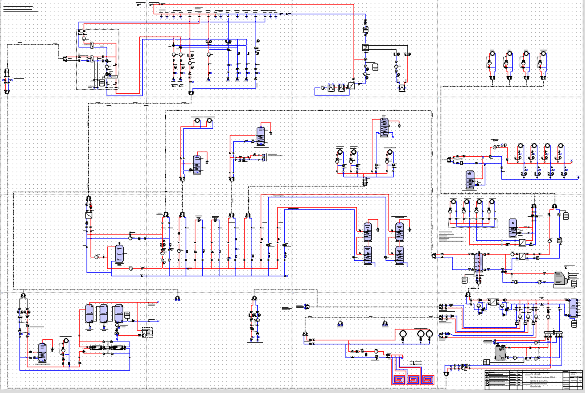
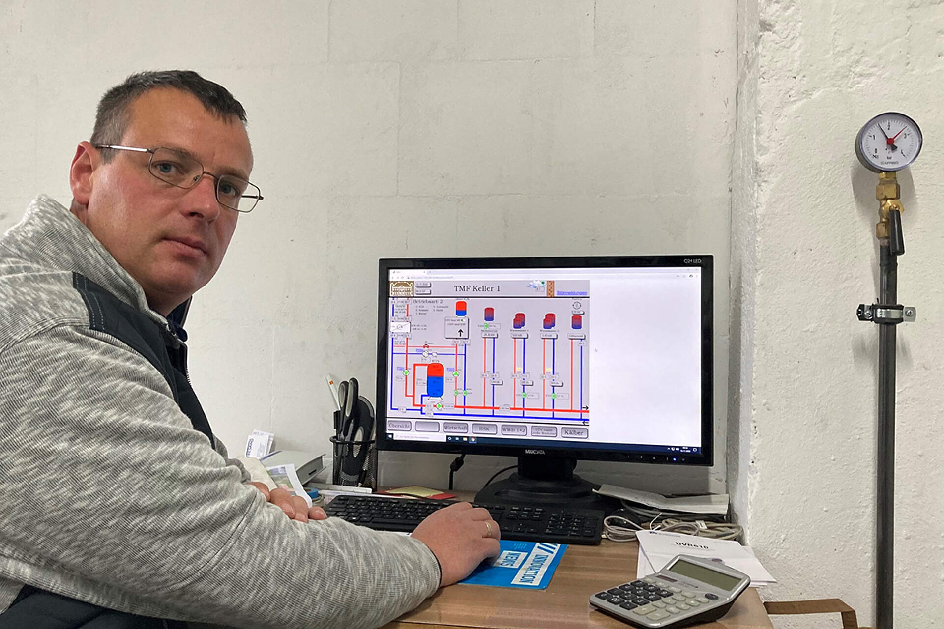
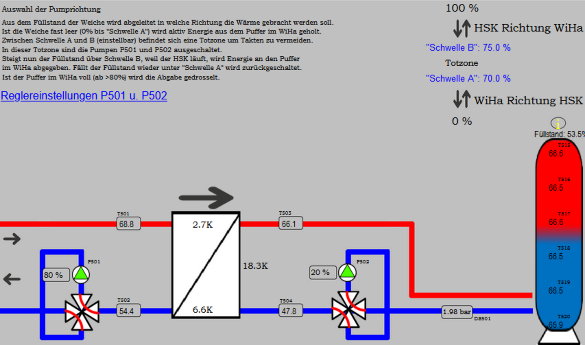
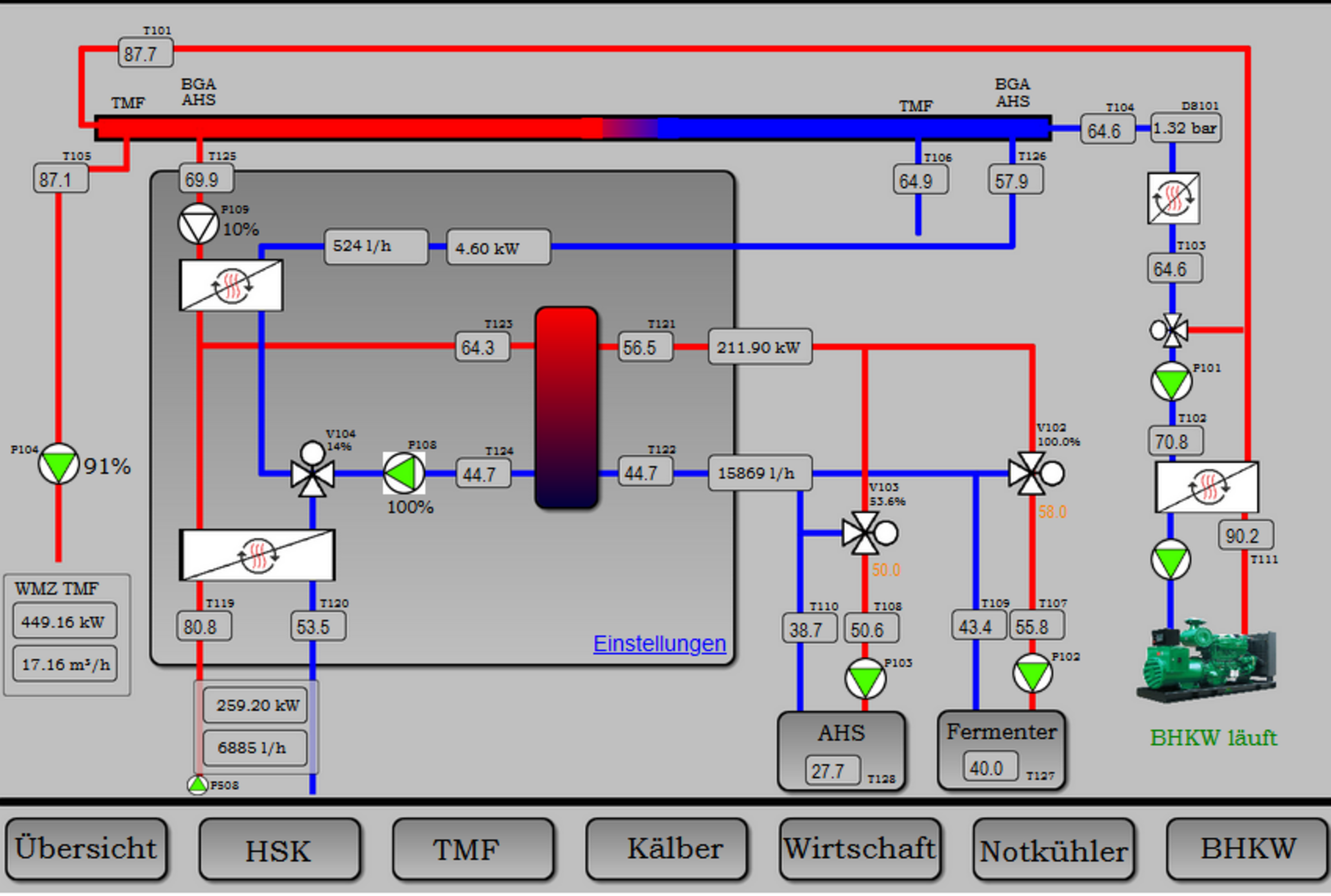
With the documentation of the entire system and new, extensive flow chart, a step-by-step implementation begun. This soon uncovered the first necessary steps to reach more effective operation. It quickly became clear that many things could be improved upon with an intelligent controller.
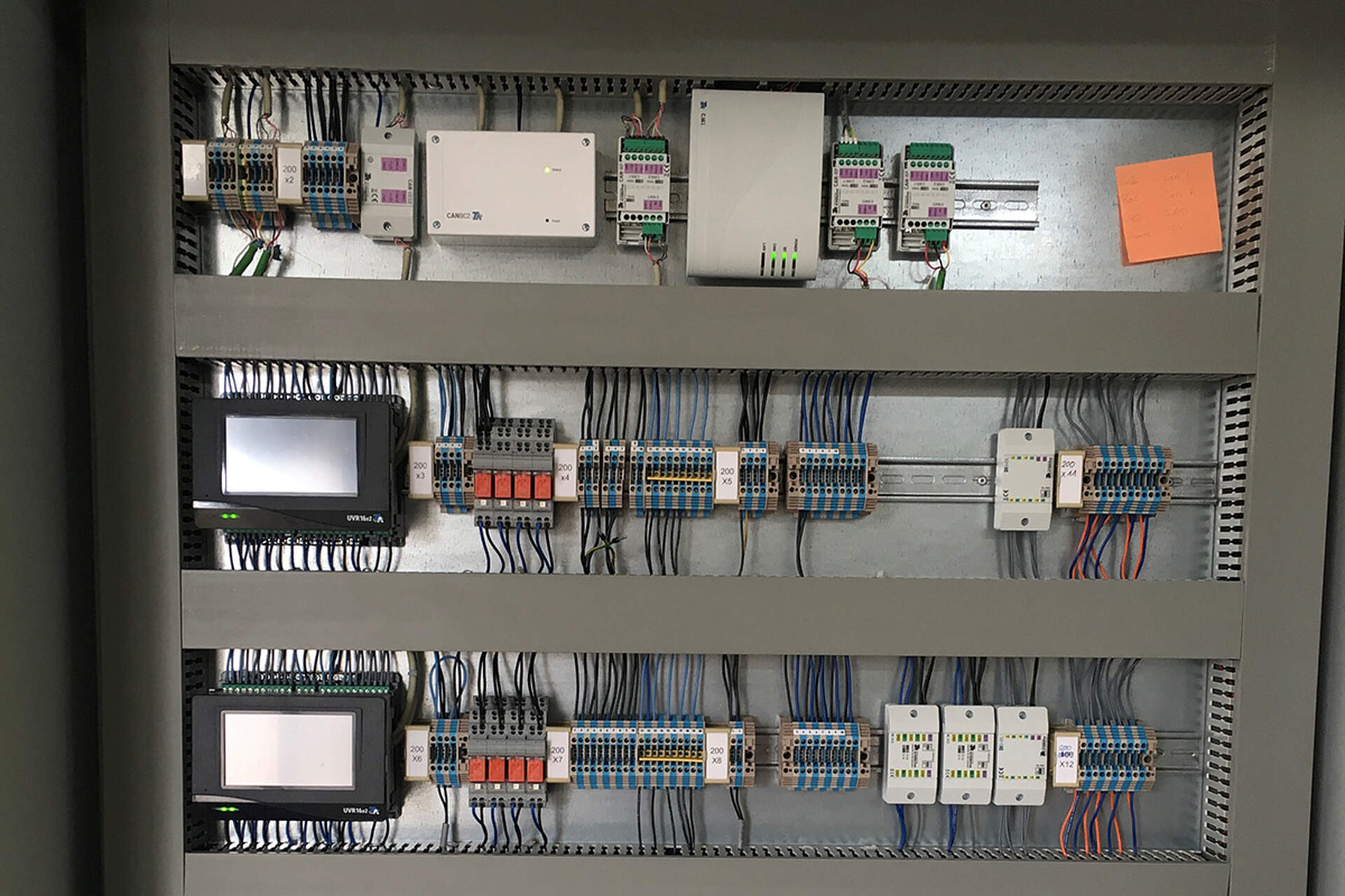
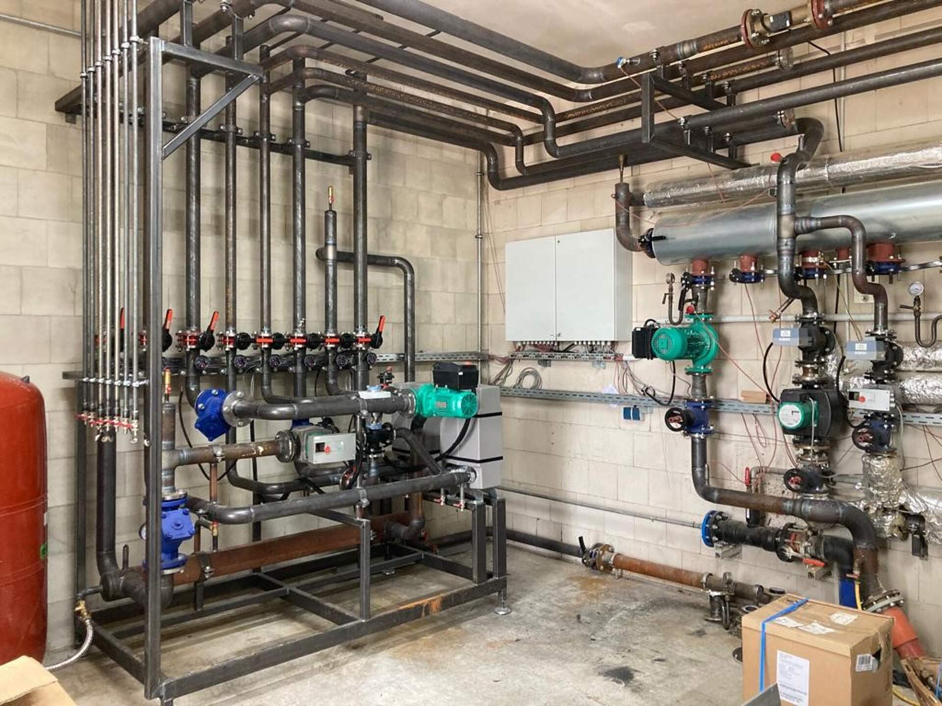
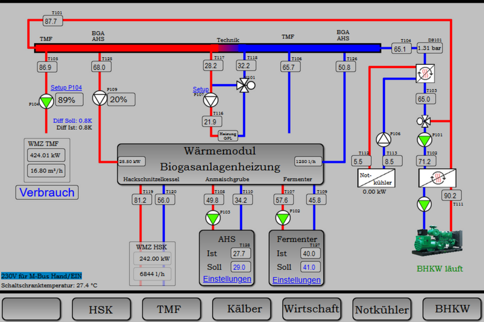
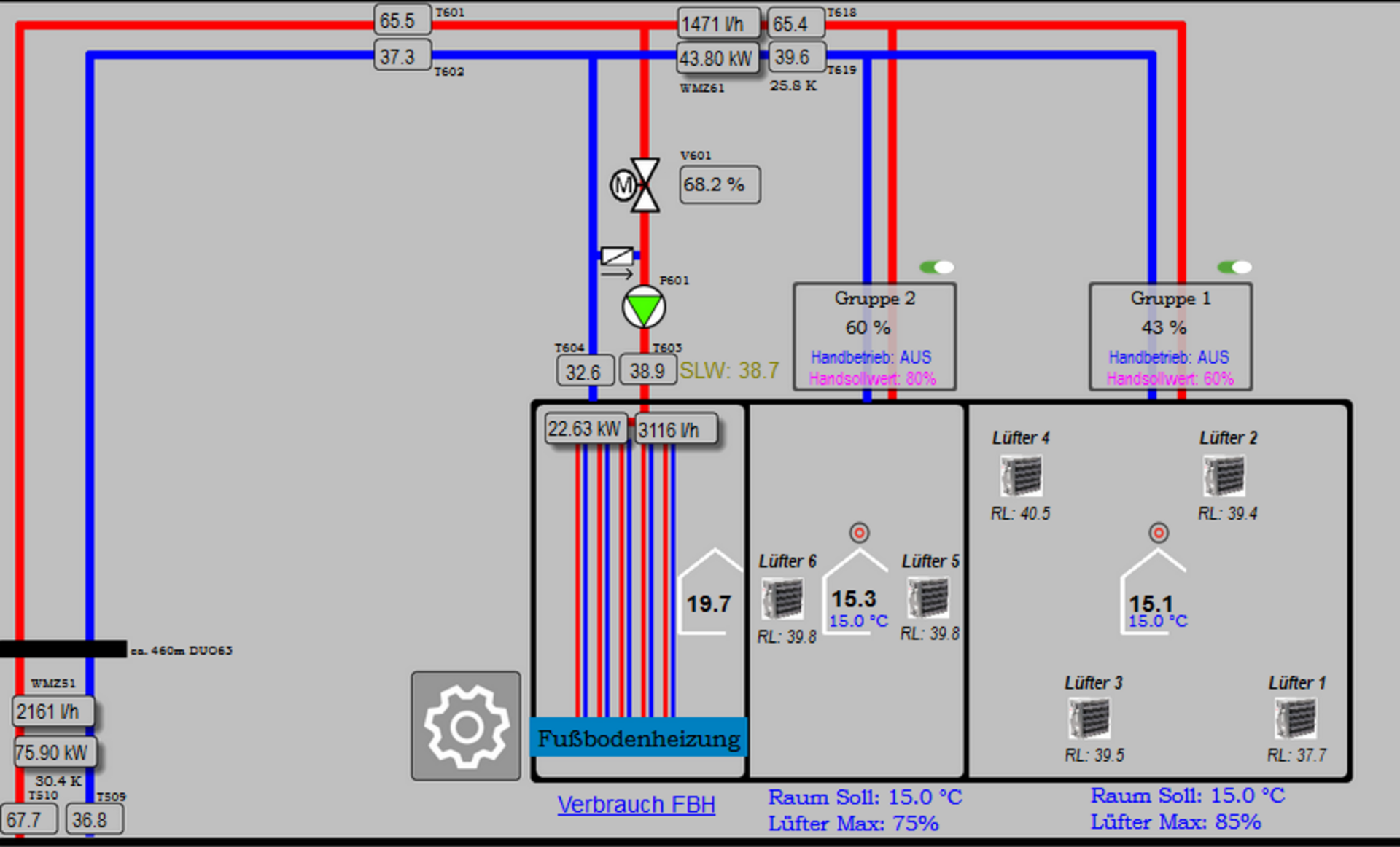
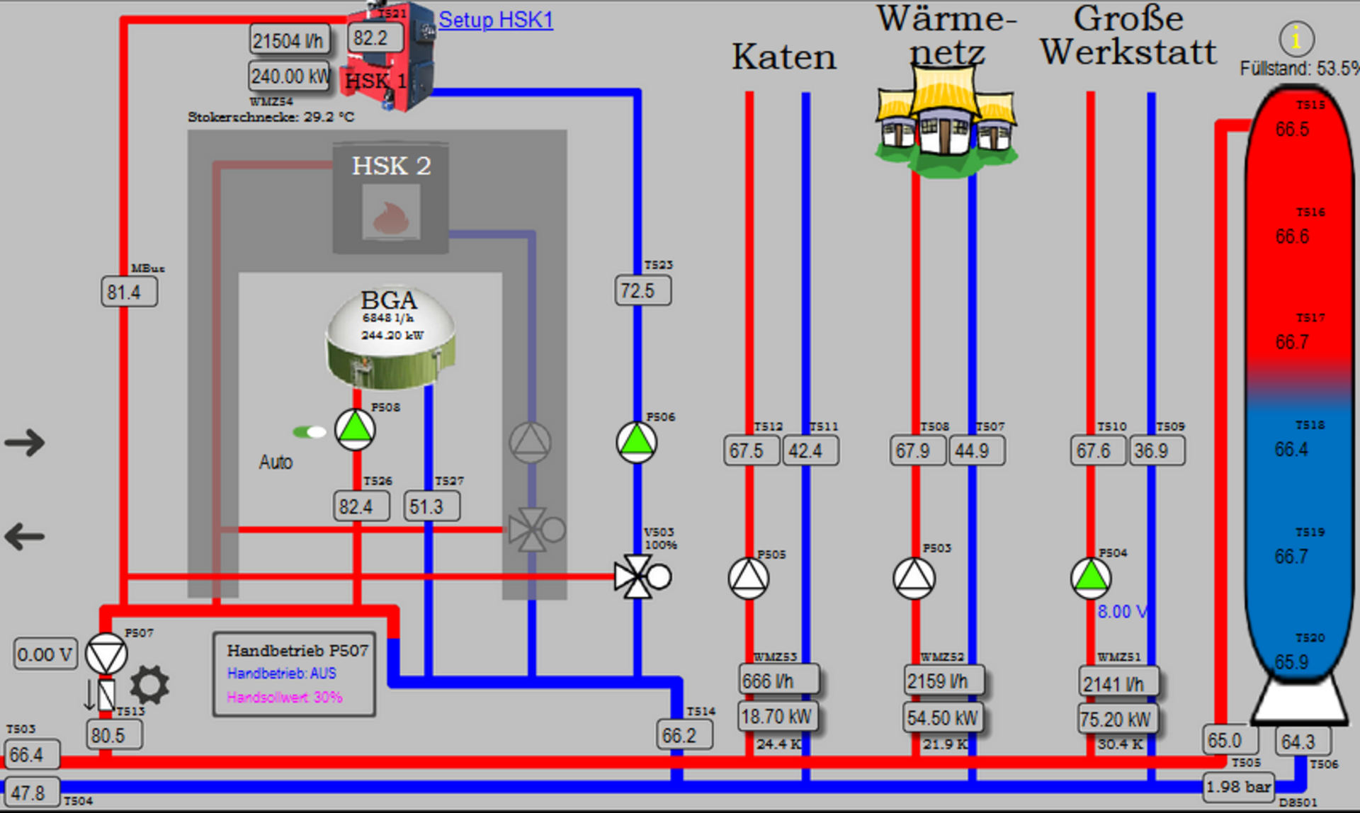
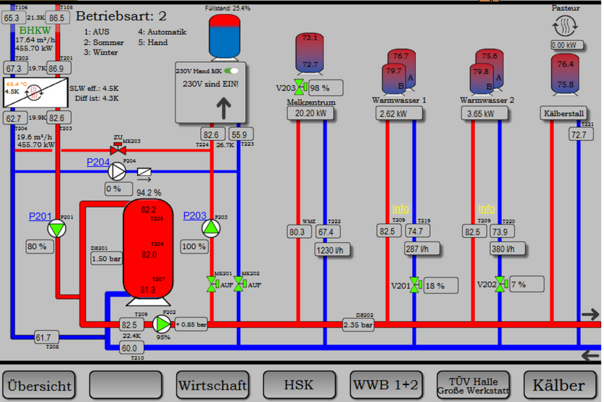
One by one, the entire system with its many locations has been equipped with Technische Alternative control technology to better utilize existing technology.
The result
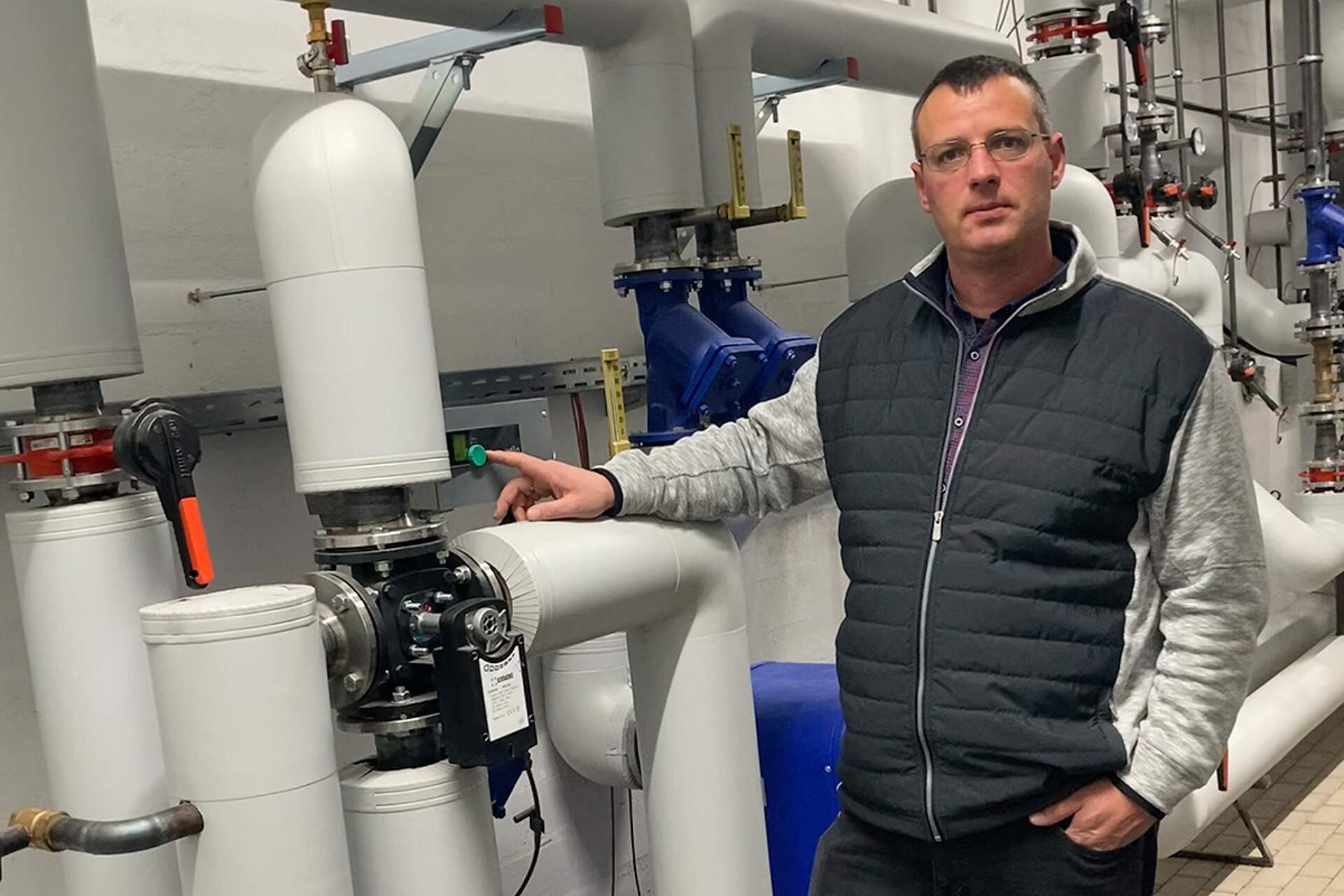
The flow temperatures now remain optimal, even with fluctuating outputs of generators and demands of consumers. The daily workload of manual input and monitoring is practically gone.
Controllers
- 7 UVR16x2S
- 5 RSM610-MB (Successor: UVR610K-OD)
- 6 C.M.I.
- 5 CAN-BC2 with M-Bus module
- 1 CAN-MTx2
- 6 CAN-UES
- 6 FTS-DL for heat metering
- approx. 20 further DL bus Extensions
- Sensory equipment
Heat generators
- CHP plant (390 kW electric, 440 kW thermal power)
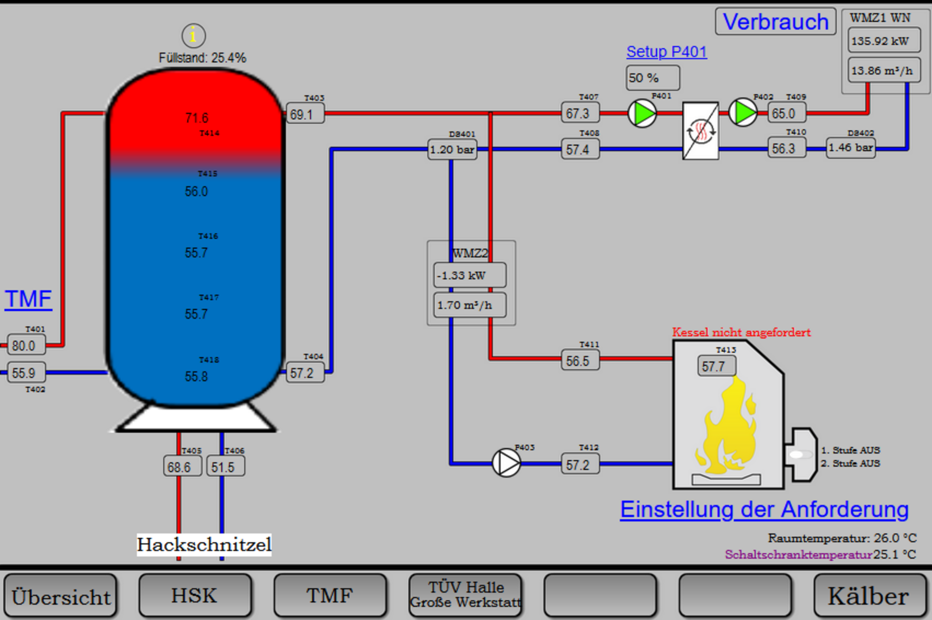
- Woodchip boiler 250 kW
- Oil boiler 380 kW
Consumers
- TMF hot water for cleaning (approx. 3x800 litres per day at 82°C)
- Calf milk pasteurisation (85°C)
- Residential and office buildings
- Workshops with underfloor heating and air heaters
- Heating network for residential buildings
- Heating of the biogas plant
Storages
Hot water tank (82 °C and up):
- TMF milking parlour 4x 600 litres
- Calf pen 1x 800 litres
- Milking parlour 1x 1000 litres
- TMF calving area 1x 600 litres
Warm water tank (55 to 60 °C):
- Manor kitchen 1x 300 litres
- Farm house 1x 300 litres
- Social area 1x 300 litres
Another 8000 litre buffer tank is used as an inert hydraulic separator, providing about 280 to 300 kW at 20K spread.
Realised by:
Planing, Programming, Support
- GPD Agrar Service und Handels GmbH, Malte Anderson
Construction and assembly
- Schweißservice Peter Niemann
- Energietechnik Satrup
